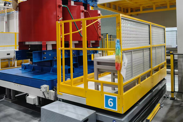
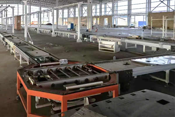
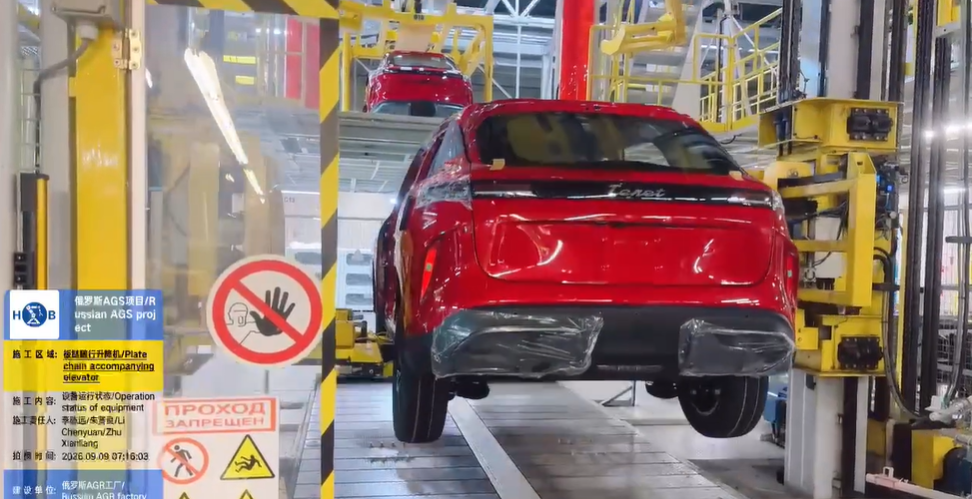
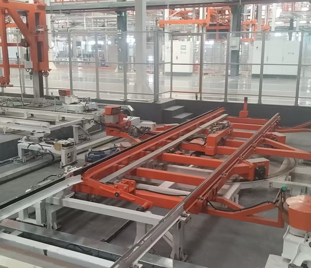
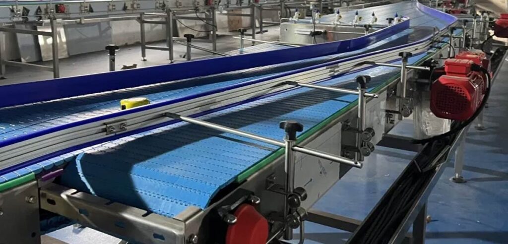
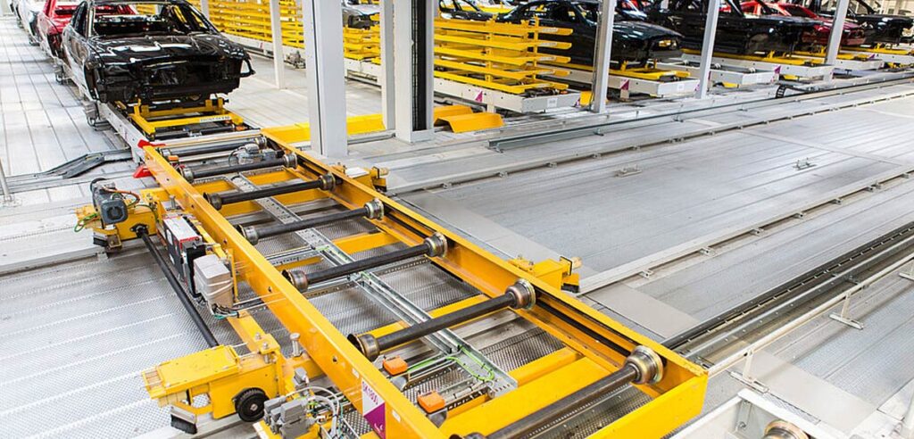
Transfer machines are used in automotive manufacturing to move workpieces, pallets, and components between different production positions or workstations. They help connect individual manufacturing processes and support the controlled movement of products through an automated assembly line.
Unlike a conveyor that continuously transports products along a fixed path, a transfer machine is often designed to perform a specific movement, such as transferring a workpiece between stations, changing its orientation, moving it into a processing position, or connecting different conveyor sections.
In automotive assembly, transfer machines can be integrated with pallet conveyors, lifting mechanisms, robots, pressing equipment, tightening systems, inspection equipment, and PLC-based control systems.
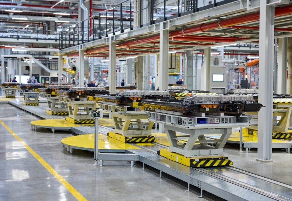
The design of a transfer machine depends on the product geometry, payload, movement requirements, cycle time, positioning accuracy, and overall production line layout.
What Is a Transfer Machine?
A transfer machine is an automated mechanical system designed to move a workpiece, pallet, fixture, or component from one position to another.
The movement may be horizontal, vertical, rotational, or a combination of different directions.
Depending on the production process, a transfer machine may perform one or more of the following functions:
- Move products between workstations
- Transfer components from one conveyor to another
- Position products for assembly
- Change product orientation
- Move workpieces into a processing fixture
- Connect parallel production lines
- Load or unload automated equipment
- Transfer products between assembly and inspection stations
A transfer machine can be designed as a standalone unit or integrated into a complete automated production line.
The main objective is to provide reliable and repeatable product movement while meeting the production cycle and process requirements.
Transfer Machine vs. Conveyor System
Transfer machines and conveyor systems are both used for material handling, but their functions are not always the same.
A conveyor is generally designed to transport products along a defined path. It may operate continuously or move products in controlled steps.
A transfer machine is usually designed for a specific movement between two or more defined positions.
For example, a conveyor may transport an engine pallet along a production line, while a transfer machine may move the pallet from the conveyor into an assembly fixture.
The distinction can be summarized as follows:
| Equipment | Primary Function |
|---|---|
| Conveyor | Transport products along a defined route |
| Transfer Machine | Move products between defined positions |
| Cross Transfer | Transfer products laterally between conveyor lines |
| Lift-and-Locate | Raise and precisely position a pallet |
| Vertical Conveyor | Move products between different elevations |
In an actual production line, these systems may work together rather than operate independently.
Why Transfer Machines Are Used in Automotive Production
Automotive manufacturing involves many different assembly, inspection, and testing processes.
The product may need to be moved between machines with different layouts, heights, operating directions, and positioning requirements.
A transfer machine provides a controlled interface between these processes.
Connecting Different Workstations
A transfer machine can move a workpiece from one workstation to another without requiring manual handling.
This helps maintain a continuous production flow.
Improving Product Positioning
Some automated operations require the product to arrive at a specific location and orientation.
A transfer machine can incorporate mechanical locating, clamping, or positioning mechanisms to meet these requirements.
Supporting Automated Production
Transfer machines can be integrated with robots, assembly tools, testing equipment, and PLC control systems.
This allows the movement of the workpiece to be synchronized with the production operation.
Reducing Manual Handling
Automated transfer equipment reduces the need for operators to manually move components between production stations.
This can improve process consistency and reduce handling-related risks.
Common Types of Transfer Machines
The appropriate transfer machine depends on the product and required movement.
Several configurations are commonly used in automotive assembly and component production.
Linear Transfer Machine
A linear transfer machine moves a workpiece along a straight path between defined positions.
The movement may be powered by an electric actuator, servo mechanism, pneumatic cylinder, hydraulic system, belt, chain, or other mechanical arrangement.
Linear transfer machines can be used for:
- Workpiece loading
- Fixture transfer
- Assembly station connection
- Machine loading and unloading
- Component insertion
- Inspection station transfer
The required stroke, speed, payload, and positioning accuracy determine the appropriate drive method.
Rotary Transfer Machine
A rotary transfer machine moves or rotates a workpiece around a defined axis.
It may be used to change the orientation of a component or move products between several processing positions.
Applications can include:
- Part orientation
- Component indexing
- Assembly position changes
- Multi-station processing
- Inspection access
- Product turning
Rotary transfer systems may use pneumatic rotary actuators, servo drives, indexing mechanisms, or custom mechanical structures.
Lift Transfer Machine
A lift transfer machine combines vertical movement with product transfer.
The mechanism may raise a pallet or workpiece, move it horizontally, and lower it into a new position.
This configuration is useful when the incoming and outgoing conveyors are arranged at different heights or when the product must be lifted away from a conveyor.
Chain Transfer Machine
A chain transfer machine uses driven chains to move pallets or workpieces between positions.
It can be suitable for heavy-duty material handling when the pallet structure is designed to interact with the chain system.
The chain configuration must be selected according to payload, transfer distance, speed, and operating frequency.
Roller Transfer Machine
A roller transfer machine uses powered rollers to move products or pallets.
It may be used when the product or pallet has a suitable flat support surface and the transfer route is compatible with roller conveying.
Roller transfer systems can be integrated with pallet conveyors and automated workstation interfaces.
Main Components of a Transfer Machine
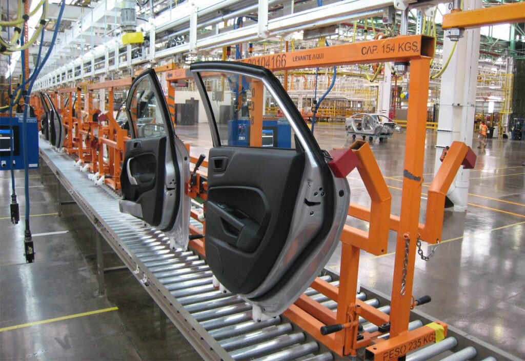
The structure of a transfer machine depends on its movement and application. However, most systems include several common components.
Mechanical Frame
The frame supports the moving mechanism, product, fixture, drive system, and sensors.
It must provide sufficient structural rigidity and maintain the required alignment during operation.
For heavy automotive products, the frame should be evaluated for both static and dynamic loads.
Transfer Mechanism
The transfer mechanism creates the required movement.
It may include:
- Linear guide rails
- Ball screws
- Chains
- Belts
- Rollers
- Rack-and-pinion systems
- Pneumatic cylinders
- Hydraulic cylinders
- Servo-driven actuators
The mechanism should be selected according to the movement profile, payload, stroke, cycle time, and positioning requirements.
Product Fixture
A fixture supports and controls the position of the workpiece during transfer.
The fixture may include locating pins, support blocks, clamps, adjustable components, or product-specific contact surfaces.
The fixture design must avoid damaging the product while ensuring sufficient stability during movement.
Drive System
The drive system provides the force required to move the workpiece.
Possible drive technologies include electric motors, servo motors, pneumatic cylinders, hydraulic systems, and motorized rollers.
The drive system should be evaluated based on the actual load, acceleration, deceleration, and duty cycle.
Sensors and Position Feedback
Sensors provide information about the position and operating condition of the transfer machine.
Typical detection points include:
- Product arrival
- Home position
- Transfer position
- Cylinder extension
- Cylinder retraction
- Fixture clamping
- Product presence
- Mechanical limit position
For applications requiring more precise motion control, encoders or servo feedback may also be used.
How a Transfer Machine Works
The operating sequence depends on the machine configuration and production process.
A typical automated transfer cycle may include the following stages.
Step 1: Product Arrival
The workpiece or pallet arrives at the loading position.
A sensor detects the product and sends a signal to the PLC.
Step 2: Product Confirmation
The system checks whether the workpiece is correctly positioned and whether the fixture is ready.
Additional checks may verify product presence, orientation, or clamping status.
Step 3: Transfer Activation
The PLC activates the drive mechanism.
The transfer machine moves the workpiece toward the target position according to the programmed movement sequence.
Step 4: Position Confirmation
The system confirms that the workpiece has reached the required location.
This may be achieved through sensors, mechanical stops, encoders, or a servo positioning system.
Step 5: Product Release or Processing
Once the transfer is complete, the workpiece may be released onto a conveyor, placed into a fixture, or delivered to an automated processing machine.
Step 6: Return to Home Position
If required, the transfer mechanism returns to its initial position and prepares for the next production cycle.
Transfer Machines in Engine Assembly
Engine assembly lines often contain multiple processes that require controlled product movement.
An engine block, partially assembled engine, or engine component may need to be transferred between conveyors, assembly fixtures, pressing equipment, and inspection stations.
Transfer machines can support operations such as:
- Component loading
- Engine block transfer
- Part orientation
- Assembly fixture loading
- Automated fastening
- Inspection positioning
- Testing station connection
For heavy engine assemblies, the transfer mechanism must be designed according to the combined weight of the product, pallet, and fixture.
The product center of gravity and required movement path should also be considered.
Transfer Machines in Transmission Assembly
Transmission assembly often requires controlled handling of housings, shafts, gears, bearings, and partially assembled units.
A transfer machine can move components between dedicated assembly equipment and inspection stations.
For example, a transmission housing may be transferred from a loading position to a pressing station, then moved to a fastening or inspection workstation.
The machine can be equipped with dedicated locating elements to ensure that the component arrives in the correct orientation.
Where a process generates mechanical force, such as pressing or bearing installation, the transfer fixture must provide sufficient support and rigidity.
Transfer Machines for Powertrain Production
Powertrain production combines several assembly, inspection, and testing operations.
A transfer machine can help connect these processes while maintaining controlled product movement.
Depending on the line configuration, the system may transfer products between:
- Assembly conveyors
- Press-fitting machines
- Tightening stations
- Leak testing equipment
- Vision inspection systems
- Functional testing equipment
- Manual workstations
- Automated loading stations
The transfer machine can be controlled by the main PLC or operate as a coordinated subsystem within the production line.
Transfer Machines for EV Component Assembly
Electric vehicle manufacturing includes components such as electric motors, reducers, drive units, and battery-related assemblies.
These products may require dedicated fixtures and specialized transfer movements.
For EV component applications, engineers should consider:
- Product weight
- Product geometry
- Electrical safety requirements
- Fixture contact areas
- Required orientation
- Positioning accuracy
- Traceability
- Integration with automated testing
A transfer machine can be customized to handle the product without interfering with electrical connectors, sensitive surfaces, or other critical components.
Transfer Machines for Automotive Parts Production
Transfer equipment is also used in automotive component manufacturing.
Potential applications include:
- Steering component assembly
- Brake component production
- Suspension assembly
- Axle assembly
- Connecting rod assembly
- Piston component assembly
- Motor assembly
- Reducer assembly
The required transfer method depends on the component size, production process, and degree of automation.
Smaller components may be transferred using compact pneumatic mechanisms, while larger components may require motorized or servo-driven systems.
Positioning and Orientation Control
Product positioning is a major consideration in transfer machine design.
A component may need to arrive at a workstation with a defined:
- X position
- Y position
- Z height
- Rotation angle
- Reference surface
- Orientation
The transfer mechanism alone may not provide all required positioning functions.
In some applications, the machine needs additional locating pins, clamps, rotation mechanisms, or a lift-and-locate unit.
The positioning method should be selected according to the process tolerance and the requirements of the downstream equipment.
For example, a robot inserting a component may require a different positioning arrangement from a vision inspection system.
Transfer Machines and Robotic Workstations
Robotic assembly systems require reliable coordination between product movement and robot operation.
A transfer machine can deliver the workpiece to the robot’s working area and establish the required orientation.
The control sequence may include:
- Workpiece arrives at the transfer position.
- Product presence is confirmed.
- Fixture is engaged.
- Transfer machine moves the workpiece.
- Destination position is confirmed.
- Robot receives a ready signal.
- Robot performs the assembly operation.
- Process result is returned to the PLC.
- Workpiece is released.
The interface between the transfer machine and robot should be defined during the system engineering stage.
Integration with Press-Fitting Equipment
Press-fitting processes often require controlled workpiece positioning and sufficient fixture support.
A transfer machine may load the component into the press-fitting station or move the component between successive operations.
The machine should be designed to avoid unintended movement during loading and unloading.
If the transfer mechanism also supports the product during pressing, the mechanical structure must be evaluated for the forces generated by the process.
In many cases, the transfer machine moves the product into a separate rigid press fixture, where the pressing operation is performed.
Integration with Tightening Systems
Automated tightening requires the workpiece and fastener to be positioned correctly.
A transfer machine can move the product into the tightening workstation and provide the required orientation.
However, the final tightening position may require a separate locating mechanism.
A typical configuration may include:
Transfer Machine → Workstation Fixture → Lift-and-Locate → Tightening Tool
The transfer machine handles movement, while the fixture and positioning system establish the required assembly reference.
This division of functions helps improve process repeatability and simplifies troubleshooting.
Transfer Machines and Vision Inspection
Vision inspection systems require a suitable relationship between the camera, lighting, and product.
A transfer machine can position or orient the product before image acquisition.
For example, a component may be rotated so that a specific feature is visible to the camera.
The transfer system may also deliver the product to a fixed inspection position.
Important considerations include:
- Camera field of view
- Product orientation
- Inspection distance
- Fixture repeatability
- Lighting conditions
- Product surface protection
- Inspection cycle time
For applications involving dimensional measurement, the positioning repeatability should be determined from the inspection requirements.
Transfer Machine Control Architecture
The PLC normally coordinates the transfer machine with other production equipment.
The control architecture may include:
- PLC
- Human-machine interface
- Motor drives
- Servo controllers
- Pneumatic valves
- Position sensors
- Safety circuits
- Robot communication
- MES communication
The PLC should manage the transfer sequence and verify that the required conditions are satisfied.
For example, the transfer machine should not start if the destination workstation is occupied or if the product has not been correctly secured.
Transfer Machine and MES Integration
In a connected production line, transfer operations can be linked to product tracking and MES.
The system may record when a product enters or leaves a workstation.
When a pallet or component is identified using RFID or barcode technology, the control system can associate the transfer event with the product record.
Relevant information may include:
- Product identification
- Production order
- Transfer time
- Current workstation
- Destination station
- Process status
- Error information
This can improve production visibility and support traceability.
The specific integration method depends on the customer’s MES architecture and communication requirements.
Cycle Time and Production Efficiency
Transfer machine cycle time includes more than the actual movement distance.
It may include:
- Product detection
- Clamping
- Lifting
- Horizontal movement
- Rotation
- Position confirmation
- Product release
- Return movement
The complete cycle should be evaluated when calculating production capacity.
For a high-volume automotive line, the transfer cycle must be compatible with the required takt time.
Engineers should also consider whether the transfer machine operates simultaneously with other workstation activities.
For example, a return movement may be performed while the next product is being prepared, provided that the safety and process requirements allow it.
Safety Considerations
Transfer machines contain moving mechanisms that can create crushing, shearing, collision, or unexpected movement hazards.
Safety measures should be included during the initial engineering stage.
Depending on the application, the system may require:
- Mechanical guarding
- Safety doors
- Safety light curtains
- Safety scanners
- Emergency stop devices
- Mechanical travel limits
- Position monitoring
- Fixture status monitoring
- Safety interlocks
- Controlled restart procedures
If the transfer machine operates near robots or manual workstations, its safety functions should be coordinated with the surrounding equipment.
The final safety design should be based on the machine configuration, operating environment, and customer requirements.
Maintenance of Transfer Machines
A transfer machine should be designed with maintenance access in mind.
Important maintenance items may include:
- Guide rails
- Bearings
- Chains
- Belts
- Ball screws
- Motors
- Gearboxes
- Pneumatic cylinders
- Hydraulic components
- Sensors
- Mechanical stops
- Fixtures
- Electrical connections
Regular inspections can identify wear, looseness, abnormal vibration, or positioning deviations before they affect production.
For high-cycle applications, the maintenance plan should specify inspection intervals and replacement criteria for wear components.
How to Select a Transfer Machine
The transfer machine should be selected according to the actual movement and production requirements.
Before designing or purchasing the equipment, engineers should define:
- What product or pallet will be transferred?
- What is the maximum payload?
- What are the product dimensions?
- What is the required movement direction?
- What is the transfer stroke or distance?
- Is rotation required?
- What is the required positioning accuracy?
- What is the required cycle time?
- Will the machine connect to a conveyor?
- Will the machine load a robot or assembly workstation?
- Are clamping or locating functions required?
- What PLC and communication interfaces are needed?
- What safety functions are required?
- How will maintenance personnel access the equipment?
These factors determine the appropriate transfer mechanism, drive system, fixture, sensors, and control architecture.
Custom Transfer Machine Design
Automotive production lines often require transfer machines that are designed around a specific component or process.
A standard transfer mechanism may not be sufficient when the product has unusual dimensions, an irregular center of gravity, tight positioning requirements, or a complex movement path.
A customized transfer machine may combine:
- Linear transfer
- Vertical lifting
- Rotary positioning
- Product clamping
- Precision locating
- Pallet handling
- Conveyor integration
- Robot communication
- PLC control
- Product tracking
The equipment should be designed as part of the complete production process.
This reduces the risk of incompatibility between the transfer mechanism and the surrounding assembly or inspection equipment.
Hongbo Transfer Machine Solutions
Hongbo Automation develops customized material handling and automation equipment for automotive assembly and automotive component production.
Transfer machines can be designed according to the product geometry, payload, movement path, cycle time, positioning requirements, and workstation configuration.
Hongbo transfer equipment can be integrated with pallet conveyors, cross transfer systems, vertical conveyors, lift-and-locate units, robotic workstations, press-fitting equipment, tightening systems, inspection equipment, and PLC control systems.
The engineering approach focuses on coordinating product movement with the actual manufacturing process.
This allows the transfer machine to function as an integrated part of the production line rather than as an isolated mechanical device.
Conclusion
Transfer machines provide controlled movement between production positions and help connect different operations within an automated automotive assembly line.
Depending on the application, a transfer machine may perform linear movement, vertical lifting, rotary positioning, pallet transfer, or a combination of these functions.
Its design should consider payload, product geometry, movement path, positioning accuracy, cycle time, fixture configuration, control architecture, and safety requirements.
When integrated with conveyors, robots, assembly equipment, inspection systems, and production tracking, transfer machines can support reliable and flexible automotive manufacturing.
For engine, transmission, powertrain, EV, and automotive component production, the most suitable transfer solution is one designed around the actual product and production process.
Frequently Asked Questions
What is a transfer machine in automotive manufacturing?
A transfer machine is automated equipment that moves a workpiece, pallet, or component between defined positions, workstations, conveyors, or processing machines.
What is the difference between a transfer machine and a conveyor?
A conveyor generally transports products along a defined route, while a transfer machine performs a specific movement between designated positions or production stations.
Can transfer machines move heavy automotive components?
Yes. The machine structure, drive system, fixture, and guides can be engineered according to the combined weight of the product, pallet, and tooling.
Can a transfer machine rotate a workpiece?
Yes. Rotary transfer machines can change a product’s orientation or move it between different processing positions.
Can transfer machines be integrated with robots?
Yes. Transfer machines can deliver products to robotic workstations and communicate with robot controllers or the main PLC to coordinate the production sequence.
Can transfer machines be used with pallet conveyors?
Yes. Transfer machines can be integrated with pallet conveyors to move products between conveyor sections, fixtures, assembly stations, and inspection equipment.
Can Hongbo customize transfer machines?
Yes. Hongbo can develop transfer machines according to product dimensions, payload, movement requirements, positioning accuracy, cycle time, workstation layout, and automation interfaces.