Chassis Conveyor System for Automotive Assembly: Types, Design, and Applications
In automotive manufacturing, chassis transportation is a critical part of the final assembly process. A chassis conveyor system moves vehicle chassis or related assemblies between workstations, allowing production operations to be completed in a defined sequence. Depending on the vehicle architecture and manufacturing process, the system may support underbody assembly, powertrain installation, suspension installation, inspection, and other production activities.
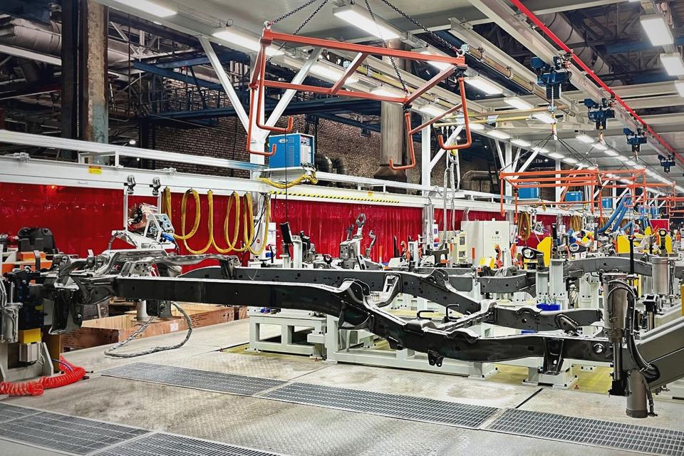
Unlike conveyors designed for small components, chassis conveying equipment must accommodate large loads, changing vehicle configurations, and demanding positioning requirements. In addition, the system must coordinate with lifting equipment, assembly tools, automated handling devices, and downstream production stations.
Therefore, selecting a chassis conveyor system requires more than determining the required conveyor speed. Engineers must consider vehicle dimensions, load distribution, production takt time, workstation access, transfer requirements, and the overall plant layout.
This article explains the main types of chassis conveyor systems, their applications in automotive manufacturing, and the key factors involved in designing an efficient and reliable solution.
What Is a Chassis Conveyor System?
A chassis conveyor system is a material-handling system designed to transport vehicle chassis, underbody structures, or chassis assemblies through automotive manufacturing operations.
The exact meaning of “chassis conveyor” varies between plants. In some applications, the conveyor transports a vehicle body or underbody structure before final assembly. In others, it handles a chassis assembly that includes suspension, axles, steering components, or other installed parts. The conveyor configuration must reflect the actual workpiece and process.
A typical system may include:
- Powered roller or chain conveyors
- Skid or pallet conveyor systems
- Lift-and-transfer equipment
- Cross-transfer units
- Lifting platforms and positioning devices
- Vehicle or workpiece locating fixtures
- Sensors and PLC-based controls
- Safety guarding and operator access provisions
- Interfaces with assembly tools and production information systems
For example, a chassis assembly may move along a conveyor to a station where suspension components are installed. It can then be transferred to another section for subsequent assembly or inspection.
In a final assembly plant, the conveyor may also be integrated with lifting equipment so that operators can access the underside of the vehicle during installation work.
The most suitable configuration depends on the chassis structure, assembly sequence, required load capacity, and the relationship between adjacent workstations.
Why Automotive Plants Need Dedicated Chassis Conveying Equipment
Chassis assemblies are often large, heavy, and difficult to move manually. Their transportation must also be coordinated with the production process, particularly when several operations are performed along the same line.
A dedicated chassis conveyor system helps establish a controlled route and provides repeatable interfaces between workstations.
Maintain Stable Production Flow
Automotive assembly lines operate according to planned production rates. If chassis transportation cannot keep pace with downstream operations, workstations may experience material shortages or production interruptions.
A properly sized conveyor system moves chassis assemblies according to the required production sequence. Where necessary, accumulation sections can separate adjacent process stages and provide limited buffering.
However, buffer capacity should be based on actual production requirements. Excessive accumulation can consume floor space and make it harder to identify the source of production delays.
Support Heavy and Oversized Loads
Chassis assemblies can have substantial mass and irregular load distributions. Conveyor frames, drive units, rollers, chains, pallets, and transfer devices must therefore be selected according to the expected operating loads.
The design should also account for dynamic conditions during starting, stopping, lifting, and transferring. Where several vehicle models share the same system, the maximum load and dimensional envelope must be considered.
Improve Workstation Accessibility
Many chassis assembly operations require access to the underside, sides, or ends of the workpiece. The conveyor must therefore be compatible with operator access, assembly tools, and any required lifting or positioning equipment.
For example, a lifting conveyor arrangement may raise a chassis assembly to a suitable working height. In another application, a floor-level conveyor may transfer the workpiece to a separate lifting platform.
The choice depends on the process sequence, ergonomic requirements, available space, and safety provisions.
Support Flexible Vehicle Production
Automotive manufacturers may produce multiple vehicle models or chassis variants on the same production line. These variants can differ in wheelbase, width, mass, and component configuration.
A flexible chassis conveyor system can accommodate the defined product range through suitable pallets, adjustable fixtures, controlled transfer points, or model-specific locating arrangements.
Nevertheless, flexibility must be engineered. The system should not be assumed to support unlimited vehicle variation without changes to the mechanical design, controls, or production layout.
Common Types of Chassis Conveyor Systems
Different conveyor technologies serve different production requirements. The selection should be based on the workpiece, load characteristics, positioning needs, and layout constraints.
1. Skid Conveyor Systems
A skid conveyor transports the workpiece on a dedicated carrier or skid. The chassis or vehicle body is supported by the carrier, which provides a standardized interface with the conveying equipment.
Skid conveyors can be used in automotive body and assembly processes where a stable transport platform is needed between stations. Depending on the layout, the system may use roller-based, chain-based, or other suitable conveying arrangements.
A skid system can also simplify the interface between the conveyor and positioning equipment because the locating features are designed around the carrier.
During design, engineers should evaluate skid dimensions, load distribution, support points, stopping accuracy, and return logistics. The carrier must remain stable during transportation and transfers while providing sufficient clearance for the required assembly operations.
2. Roller Conveyor Systems
Powered roller conveyors move workpieces or carriers along a defined route through rotating rollers. They can be suitable for applications where the chassis assembly is supported on a compatible pallet, skid, or transport fixture.
Roller conveyors are useful for straight transportation sections and can be combined with accumulation zones and transfer units.
However, the conveyor must be designed for the actual load and support arrangement. Roller spacing, shaft capacity, frame stiffness, drive configuration, and stopping devices all influence system performance.
Where accurate positioning is required, the conveyor may need additional locating equipment at the workstation rather than relying on conveyor movement alone.
3. Chain Conveyor Systems
Chain conveyors are commonly used for transporting pallets, skids, and other carriers in industrial production environments.
In chassis handling applications, the chain system moves the loaded carrier through the required process route. It may also connect assembly stations, accumulation sections, and transfer equipment.
The design must account for the total carrier and workpiece mass, chain loading, drive torque, operating speed, and maintenance requirements. In addition, the system should provide practical access to drive components and wear parts.
For heavy-duty applications, load calculations and mechanical validation are essential. The final configuration should be selected according to the actual operating conditions rather than relying solely on a general conveyor category.
4. Lift-and-Transfer Systems
A chassis conveyor line may need to move a workpiece between parallel conveyor sections or change its elevation to connect different process stages.
Lift-and-transfer equipment can raise a loaded carrier, transfer it to another route, and lower it into position. This arrangement is useful when a plant layout requires branch routes or when different operations take place at different elevations.
The equipment must be coordinated with the connected conveyors so that transfers occur only when the receiving section is ready.
Important design factors include rated load, lifting stroke, transfer distance, positioning tolerance, cycle time, safety interlocks, and maintenance access.
5. Lifting and Positioning Conveyor Systems
Some chassis assembly operations require the workpiece to be raised or positioned for installation, inspection, or fastening.
A lifting conveyor or integrated lifting platform can bring the chassis assembly to the required working height. Depending on the process, the system may also include locating pins, mechanical stops, or other positioning features.
This arrangement can improve access to the workpiece and support more consistent assembly conditions. However, lifting equipment must be designed around the load distribution, required movement, workstation layout, and applicable machinery safety requirements.
The conveyor and lifting device should be engineered as a coordinated system, particularly where the next operation depends on a repeatable workpiece position.
How a Chassis Conveyor System Works
Although configurations vary, a typical chassis conveyor system follows several stages.
Step 1: Loading and Workpiece Positioning
The chassis or underbody assembly is loaded onto the designated carrier or support structure. Depending on the application, loading may be performed manually, by a lifting device, or by automated handling equipment.
The loading station must ensure that the workpiece is correctly supported before transportation begins. Where different chassis variants share the same line, the system may also need to verify the carrier type or workpiece identity.
Step 2: Transportation Along the Production Route
The conveyor moves the loaded carrier toward the next workstation. Sensors detect carrier presence and provide feedback to the PLC-based control system.
The control logic determines whether the next conveyor section is available and whether the workpiece can proceed. If the downstream station is occupied, the system can hold the carrier at a defined stopping point.
This approach helps coordinate material movement with production demand and prevents conflicting conveyor operations.
Step 3: Transfer Between Conveyor Sections
When the production layout requires a change of direction or elevation, a transfer device moves the carrier to the next route.
Before a transfer begins, the control system should confirm that the carrier is correctly positioned, the receiving section is ready, and the required safety conditions are satisfied.
Following the transfer, sensors can confirm the new carrier position so that the next conveyor section can operate according to the defined sequence.
Step 4: Positioning for Assembly Operations
At the workstation, the chassis assembly may be stopped at a defined position for assembly, fastening, inspection, or other operations.
Where greater positioning accuracy is required, a separate locating or lifting mechanism may secure and position the workpiece. This is particularly important when assembly tools or automated equipment must operate at repeatable locations.
The required accuracy should be specified according to the actual process. Conveyor stopping accuracy and workstation locating accuracy are related but should not be treated as the same requirement.
Step 5: Release and Downstream Delivery
After the workstation completes its operation, the control system confirms that the equipment is ready for the next cycle. The conveyor then releases the workpiece toward the downstream process.
If an assembly tool, lifting device, or transfer mechanism has not returned to its safe operating state, the conveyor should remain inhibited until the required conditions are met.
This interlocked sequence helps reduce the risk of equipment interference and supports predictable production flow.
Key Design Considerations for a Chassis Conveyor System
A reliable chassis conveyor system requires coordination between mechanical engineering, process planning, controls, and plant layout.
Load Capacity and Workpiece Geometry
The system must support the maximum expected chassis or carrier load, including any components installed before transportation.
Engineers should evaluate load distribution, center of gravity, support points, overall dimensions, and the effects of starting, stopping, and transferring. If several vehicle variants use the same line, the design envelope must cover the specified product range.
Where the workpiece is supported on a skid or pallet, the carrier itself must also be included in the load calculation.
Production Takt Time and Throughput
The conveyor must support the required production rate while allowing sufficient time for transfers, positioning, and workstation operations.
Throughput calculations should consider more than conveyor speed. Loading time, lift cycles, transfer duration, station occupancy, and recovery from minor interruptions can all affect effective capacity.
If a chassis assembly requires several operations at different stations, the conveyor layout and buffer strategy should be coordinated with the complete process sequence.
Positioning Accuracy
Some operations can be performed while the workpiece is moving, whereas others require it to stop at a repeatable position.
Where precise assembly is necessary, the system may require mechanical locating features or a dedicated positioning station. The required tolerance should be established with the process and equipment engineers.
For automated fastening, inspection, or robotic operations, the conveyor interface must also be compatible with the equipment’s working envelope and operating sequence.
Plant Layout and Maintenance Access
Chassis conveyors often occupy substantial floor space and may connect multiple assembly areas. The layout should account for building columns, walkways, operator access, adjacent machines, and future expansion.
Transfer units and lifting devices should be positioned to minimize unnecessary movement while maintaining access for maintenance. In addition, the design should consider how equipment can be inspected or replaced without requiring extensive dismantling of adjacent systems.
Controls and Equipment Integration
The PLC coordinates conveyor movement, transfer units, lifting mechanisms, sensors, and workstation interfaces.
The control design should define normal operating sequences, interlocks, fault responses, and restart procedures. Where production tracking is required, the system may also exchange information with MES or other plant-level systems.
Not every application requires the same degree of digital integration. The required interfaces should be determined by the production process and traceability needs.
Safety and Maintainability
Chassis conveyor systems may involve heavy moving loads, chains, rollers, lifting devices, and transfer mechanisms. A suitable risk assessment should identify hazards during normal operation, loading, fault recovery, and maintenance.
Depending on the application, protective measures may include guarding, interlocked access, emergency-stop devices, safe isolation procedures, and defined manual operating modes.
Maintenance requirements should be considered from the beginning. Accessible drive components, clear diagnostic messages, and documented recovery procedures can help reduce troubleshooting time.
Chassis Conveyor System vs. General Assembly Conveyor
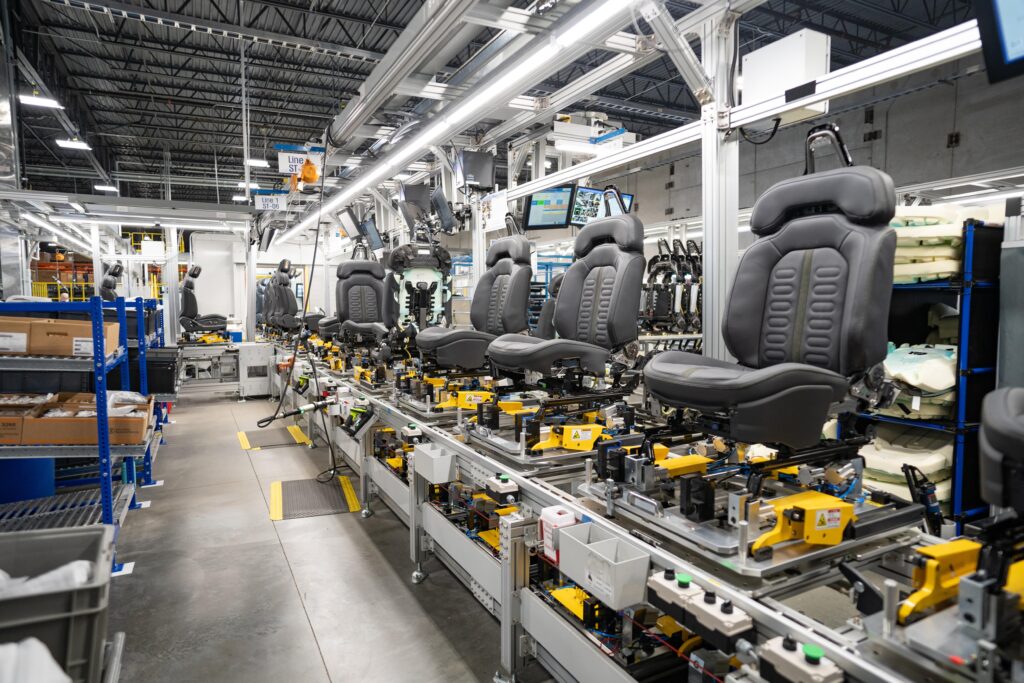
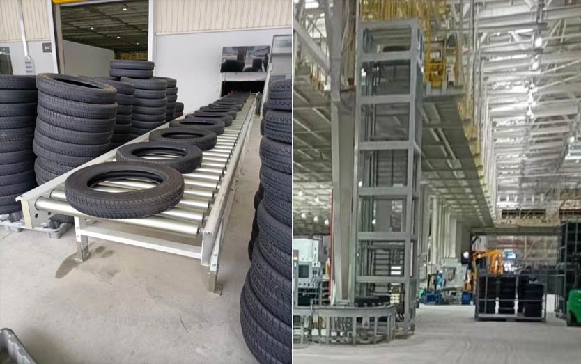
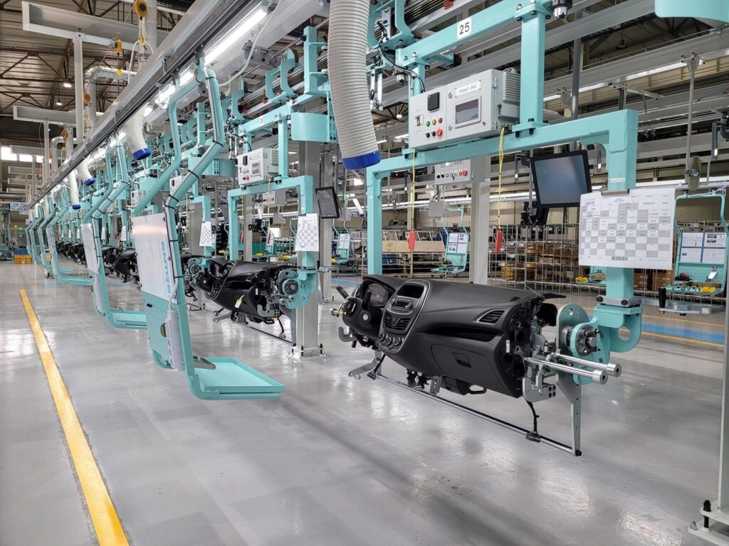
A chassis conveyor system is designed around the geometry, load, and process requirements of chassis-related workpieces. General assembly conveyors may instead transport smaller components, seats, tires, instruments, or other materials.
| Evaluation Factor | Chassis Conveyor System | General Assembly Conveyor |
|---|---|---|
| Typical workpiece | Chassis, underbody, or chassis assembly | Components, pallets, or smaller assemblies |
| Load requirements | Often requires dedicated heavy-load engineering | Depends on the transported product |
| Carrier design | May use a skid, pallet, or dedicated fixture | May use standard pallets or product-specific carriers |
| Positioning | Can require precise positioning for assembly operations | Depends on the downstream process |
| Transfer equipment | May require lifting and heavy-duty transfer units | Uses equipment sized for the relevant load |
| Integration | Often coordinated with chassis assembly and lifting equipment | Integrated with the corresponding production stations |
The actual difference depends on the workpiece and process. A conveyor should be selected according to its engineering requirements rather than its name alone.
Common Challenges in Chassis Conveyor Projects
Inadequate Load and Structural Design
If the system is not designed around the maximum workpiece and carrier load, excessive deflection, premature wear, or unreliable movement may occur.
To reduce this risk, engineers should verify load cases, support conditions, drive sizing, and transfer loads during the design stage.
Poor Workpiece Positioning
A chassis assembly may reach a station but still require manual adjustment before the next operation can begin.
The solution is to define the required positioning accuracy and determine whether conveyor stopping is sufficient or whether a separate locating mechanism is necessary.
Transfer Synchronization Problems
A lift-and-transfer unit may cause delays if it is not properly synchronized with the connected conveyor sections.
Clear interface definitions, equipment-ready signals, interlocks, and fault-recovery logic should be established before commissioning.
Insufficient Maintenance Access
Heavy-duty conveyor components can be difficult to inspect if they are installed in confined or obstructed areas.
The layout should provide practical access to drive units, bearings, chains, sensors, lifting mechanisms, and other serviceable components.
Unclear Fault-Recovery Procedures
A minor sensor or transfer fault can interrupt production if operators do not know how to restore the system safely.
The control system should provide clear fault messages and documented recovery procedures. Any manual intervention must follow the established safety requirements.
How to Select a Chassis Conveyor System Supplier
Supplier selection should consider engineering capability, application experience, integration quality, and long-term support.
Automotive manufacturing experience: The supplier should understand chassis handling, assembly processes, and the interaction between conveyor systems and production workstations.
Mechanical design capability: The supplier should be able to develop suitable conveyors, carriers, transfer units, and lifting mechanisms based on the specified load and layout.
Controls integration: The proposal should explain how conveyor sections, lifting equipment, sensors, and downstream machines will communicate.
Layout and capacity planning: The supplier should demonstrate how the system will meet the required production rate while providing adequate access, buffering, and maintenance space.
Safety and maintainability: The design should address foreseeable hazards and provide practical access for inspection, adjustment, and component replacement.
Installation and commissioning support: The project scope should clearly define installation responsibilities, control integration, functional testing, operator training, and handover documentation.
Before requesting a quotation, manufacturers should provide the available layout, workpiece dimensions and weights, required throughput, process sequence, workstation requirements, and relevant equipment interfaces. These inputs help the integrator develop a more accurate technical proposal.
Chassis Conveyor Solutions from Hongbo Automation
Hongbo Automation provides automotive production-line and material-handling solutions designed around manufacturing process requirements. For chassis conveyor projects, the system concept can be developed according to the workpiece characteristics, required throughput, plant layout, and interfaces with adjacent assembly equipment.
Depending on the project scope, the solution may include conveyor sections, carrier handling, transfer equipment, lifting platforms, positioning mechanisms, and PLC-based control integration.
The engineering objective is to establish a coordinated material flow that supports the required assembly sequence while maintaining practical operating and maintenance conditions.
For automotive manufacturers planning a new production line or upgrading an existing chassis handling process, early coordination between production engineering, equipment suppliers, and system integrators can help clarify interface requirements and reduce implementation risks.
Frequently Asked Questions About Chassis Conveyor Systems
What is a chassis conveyor system used for?
A chassis conveyor system transports chassis structures or related assemblies between automotive manufacturing and assembly stations. Depending on the process, it may also support lifting, positioning, transfers, and controlled accumulation.
Which conveyor type is suitable for chassis handling?
Skid conveyors, roller conveyors, chain conveyors, and lift-and-transfer systems may all be suitable for specific applications. Selection depends on workpiece load, dimensions, positioning requirements, production rate, and factory layout.
Can a chassis conveyor system handle different vehicle models?
Yes, provided the system is engineered for the specified range of vehicle dimensions, loads, carriers, and process requirements. Depending on the variation, the design may require different fixtures, adjustable locating arrangements, or model-specific control logic.
Does a chassis conveyor system require lifting equipment?
Not every system requires lifting equipment. However, lifting platforms or lift-and-transfer devices may be needed when the process requires changes in elevation, improved workstation access, or transfer between different conveyor levels.
How is a chassis conveyor integrated with assembly equipment?
Integration typically involves defined mechanical interfaces, sensors, PLC control sequences, and equipment-ready signals. Where required, the system may also exchange production information with MES or other plant-level systems.
What information is needed to design a chassis conveyor system?
Key inputs include workpiece dimensions and weight, carrier design, required production rate, process sequence, plant layout, positioning requirements, transfer conditions, and interfaces with adjacent equipment.
Conclusion
A chassis conveyor system is a key part of automotive material handling when chassis structures or related assemblies must move through multiple production operations. By combining suitable conveyor technology with engineered carriers, reliable transfer equipment, accurate positioning, and coordinated controls, manufacturers can establish a more predictable and organized production flow.
The best solution depends on the actual workpiece, assembly process, production rate, and plant layout. With these factors defined early, a properly engineered chassis conveyor system can support reliable transportation, improve workstation coordination, and provide a maintainable foundation for automotive assembly operations.